This guideline is easy to remember because the numbers are all one with the decimal point in a different place. If measuring in displacement, then 1.0 mil peak-to-peak is a good balance level to strive for, and it is repeating the decades-old historical level that has worked well. The best that can be achieved, when bearings are new, shafts straight, pulleys round, no looseness, small misalignments, and no resonance, is 0.1 mil.
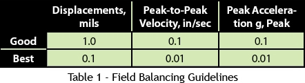
If measuring in acceleration, then 0.1 g is an acceptable balance level, and is equivalent to the 10-percent rule. The best that is normally achievable is 0.01 g acceleration.
When measuring vibration in velocity units, then 0.1 in/sec is a good balance, with 0.01 in/sec the best achievable. In velocity, the 1x-rpm amplitude should not be the dominate peak in the spectrum out to 10 times rotating speed. All of these numbers are filtered amplitude readings at rotating speed, and apply at the bearings for all three orthogonal directions – horizontal, vertical, and axial.
In field balancing, the correction is not for less-than-perfect manufacturing, but for other reasons. The rotor can have material buildup (dirt or grease on fans) or material loss (erosion on coal-ash fans), bearing changes that affect the center of rotation, shaft distortion due to residual stress relaxation, structural changes, or speed increases. The machine is usually in a service posture and there is a narrow window of time opportunity to do balancing. The goal in field balancing is to reduce the 1x-rpm vibration amplitude to be as small as reasonably achievable in the allotted time. Time sometimes becomes the balance guideline in field work, because when the allocated time is exhausted, then that defines the end of the job. The numbers shown in Table 1 should not be considered as hard limits. Remember, the purpose for mass balancing is to reduce the centrifugal forces that beat up bearings, and also to reduce the transmitted forces causing collateral damage or discomfort. If the machine only needs to operate for six more months until a planned replacement, then there is no need to fine balance to extend the bearing life. I might accept 0.2 g as acceptable if further reduction proved difficult in the allotted time. Many machines have operated at 5 to 10 times the levels in Table 1 for short periods, like several weeks, with some wear, but they survived.
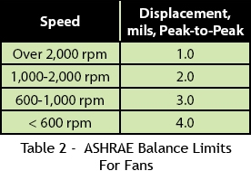
Some industries have developed clear balance guidelines for their class of machines. We spend more time balancing fans in the field than any other machine. The American Society of Heating, Refrigerating, and Air Conditioning Engineers (ASHRAE) has long used the balance limits in Table 2.
Cooling-tower manufacturers have used 5.0 mils measured horizontally at the base of the gearbox as their field balance standard. I have been successful at balancing about 50 cooling-tower propellers to less than 2.0 mils when measuring at the top of the gearbox.
Diesel-engine manufacturers have also used 5.0 mils measured horizontally on the casting at the centerline of the crankshaft as the definition of an acceptable engine.
Good ones typically measure 1.0 to 2.0 mils when everything is firing properly. A recent international standard, ISO 8528-9, defines acceptable vibration on engine-driven generator sets in terms of overall RMS vibration in displacement, velocity, or acceleration in the frequency range of 10 to 1,000 Hz.
Indeed, this has been the trend among trade associations, to depart from filtered amplitude readings in displacement to judge balance, and replace it with overall velocity to judge acceptance in the field at the time of startup. This encompasses other vibrations in addition to unbalance, like vane passing frequencies, misalignment, bearings, and especially structural resonances. The Hydraulic Institute (for pumps) and the Air Movement and Control Association (for fans) have revised their balance and vibration standards to be in overall velocity. This happened in the mid-1990’s.